
 Continue with onX Maps
 Sign in with Facebook


What is the worst thing about YOUR tool?


|
|
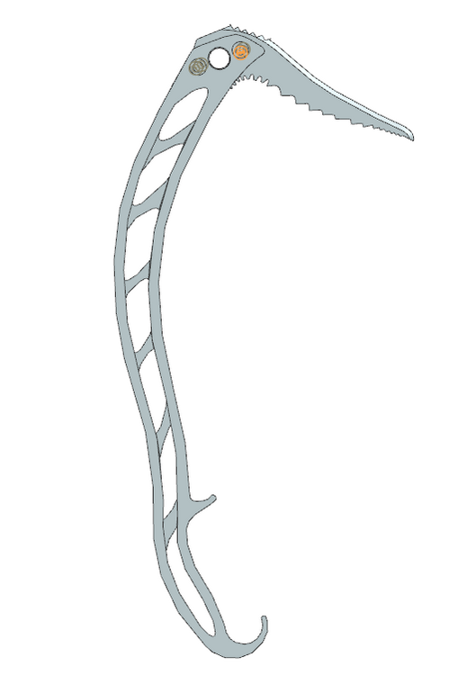
I am designing ice tools to machine out of 7075 billet. 3rd year ME @ MI Tech, somehow got approved to do this shit on my own for credits !!! Currently I am going with a primary grip angle similar to a Nomic with an overall shape more like a North Machine/Salamandra. What is the worst thing about your current tools? (and what tool?). I am hoping to create something significantly lighter and stronger than modern 3 piece hydroformed tools that would make the increased cost of solid aluminium worth it in the long run. I like my Nomics. but I feel that sometimes I have to "flick" really hard and it's not a natural throw into the ice. X-dreams swing real easy but they look dumb AF. OG quarks are cools but heavy, and X-15s (orange bent shaft no leash) look nice but sometimes bounce. Pls rate my current design on looks only. (aesthetics sell) I am going to do lots of FEA and optimize the cross bracing, but it does not really matter bc forces of ice climbing are so low (A 1000lb force reaches 1/2 the yield strength of 7075 on my current design) |
|
|
 |
|
|
Following. Very cool to see other machinists/climbers. |
|
|
Pick in picture is about 1" longer than petzl |
|
|
On a machined tool I would like to see some kind of bumper in the areas where I'm going to be scratching and hitting it most. I imagine you could design some rubber plugs or something to go in the cut-outs which could achieve this and also reduce vibration transmission. Good luck, sounds like a cool project! |
|
|
Looks similar to the Grivel Machine 3.0 design. although that was forged and not CNCd  you will probably want something additional on the handle area so that you arent directly grabbing cold metal in freezing temps. |
|
|
This is a cool project and a great exercise for a student who is also a climber, here are a few things to consider that might not be immediately obvious from the academic perspective (they would not have been obvious to me when I was a student, that's for sure): Houghton Gremlin wrote: Be careful about your expectations. It may be difficult to be significant lighter AND stronger than a hydroformed tube using a CNC structure. In particular, note stress risers and potentially poor grain structure in a CNC machined component.
It might be worthwhile to do some experimentation to determine actual forces at work on a climbing tool. It might not be true that they are "low" (what does low mean, without context?). There are various complex forces at work, especially with impact loading (swinging, hammering) and more complex bending/torsion (torquing picks, multi-point contact, etc.) In either case, you will want to validate your FEA results somehow to verify that they are accurate. It's very, very easy with modern tools to generate quick FEA results that look plausibly correct; it's much harder to set up loads and constraints that are representative of real world, and a mesh that gives accurate results in the critical small areas where stress riser occur. Consider instrumenting a test tool and correlating FEA results with measured data. As a bonus, this will give you some data acquisition experience, which is a great skill to add to your academic resume. |
|
|
Kyle Tarry wrote: Personally I would never climb with a billet machined tool for this reason. It is the wrong application for the method. |

|
I recently got a pair of Kailas Entheos II , which are CNCed, and have been loving them. Only potential issues are no hammer (not related to shaft design though I know) and the secondary grip is cold to handle (just a bit of grip tape covering the aluminum). They’re slightly lighter than my older Vipers, and feel indestructible so far. I think the geometry is pretty similar to nomics. |
|
|
I ice climb on ice tools that I designed myself, and I've learned two major things. First, the shaft-pick interface is difficult to get right and you need either 1) very tight tolerances or 2) clever design to ensure that interface stays rigid and the pick doesn't have any play relative to the shaft. Remember that threaded fasteners should not be used to constrain/define position, you'll need a pin or a keyway or something else to rigidly constrain the position of the pick. It looks like your design uses petzl(?) picks which have that little step, so make sure you get the manufacturing of that feature correct. Secondly, lighter is very often not better. You're right that loads are relatively small (assuming perfect use and only pure ice climbing) so it's easy to design a tool that is very light. However, light tools can really suck to use. My tools are made out of carbon fiber, probably about half the weight of the various hydroformed aluminum tools, and they kinda suck to use on even slightly hard ice. Very bouncy. So in regards to that, I would recommend focusing on other aspects outside of weight that you could improve with your design, as lower weight is probably not better. Maybe making them adjustable in some manner so they could be comfortably used on vertical ice and mountaineering/glacier travel? |
|
|
Ian Bales wrote: It's totally fine to use screws/bolts to constrain position, with the important nuance that you want to use the squeezing force of the bolted joint to hold the assembly together via friction, and not to shear load the fasteners (which will happen if the joint is loose, or has insufficient compression due to undersized or under-torqued fasteners). Bolted joints hold together all manner of things in this fashion (steel building structures, automotive assemblies, train parts, machinery, etc.). Screws aren't great for setting position on critical assemblies, but I don't know if an ice tool is critical in this sense. Grivel tools (what I am most familiar with) use the screws to both locate and retain the picks, and it seems to work fine. This is an awesome side quest for an engineering student, because bolted joints and assembly tolerances are often not covered will in academia. Understanding tolerance stackup, aternative locating schemes (i.e. dowel pin/slot, etc.), and understanding how to evaluate a bolted joint, are all SUPER useful skills to have in industry. |
|
|
This is an awesome project and I wish you great luck! In addition to Kyles great advice, there are standards all ice tools on the market abide by for them to be sold in most markets- and those standards are usually certified by testing requirements that must be passed (in the industry, tools are sent to 3rd party testers) A summary of the standards published by UIAA (the only publicly available ones I know) are here: https://www.theuiaa.org/documents/safety-standards/Pictorial_UIAA152%20Ice%20Tools.pdf - there are also other certifying standard organizations for Ice tools that may overlap with the aforementioned standard or have additional tests. Keep in mind, these are the minimum standards a tool must abide by to be sold on market. Most companies that want to make a reliable tool may have internal standards higher than those mentioned and some other tests such as fatigue life that are not specified in the standards aforementioned. Many of these tests can be replicated in CAD and FEA analysis to get a general idea of the design and guide your design process. But, if you can manufacture multiple tools and test them in the same manner such as the UIAA tests would be done in - that would prove the integrity of your design (or learn where design iteration may need to be done). Side note: your screenshot looks like solid works, so if you want to get really fancy - you can use topology optimization built in to the simulation suite to have a computer optimize your design. You can look up videos online on how to do this. |
|
|
While billet CNC machining is awesome, IMHO hydroformed and forged aluminum, and especially carbon fiber, is better suited to ice tools. What you’re doing is the easy and fun part. As others have mentioned, a final product is a completely different animal, (not that that’s your ultimate goal.) You’ve got to anodize, figure out the handle, account for the pick attachment, and most importantly, test. That’s the hard part. In any case, looks like a great project. Best of luck! I am an experienced machinist and hack ice climber. G41 (left cutter comp, climb mill) forever baby! |
|
|
This is a pretty cool thread and a good looking initial design. The main points already raised that I agree with are: 2. head to pick connection is indeed not trivial and achieving low tolerances is quite expensive when working with super hard steel 3. heat conductivity of aluminium is horrible for ice climbing, so you need to think of a solution to his problem for the handle On top of this: 1. Impact energy is actually quite high when ice climbing; not saying that the tool would break, but if it absorbs energy it makes swinging less efficient 2. IMO lighter is better however you do have to primarily consider climbing experience, not just weight saving. It's entirely possible to design a lighter tool that will climb worse. For ice you want to minimize total mass while maximizing the moment of inertia around the handle and around the tip of the pick. I suspect getting down to 500g with reasonable performance should be possible. 3. You need lateral strength. It is not measured by UIAA tests, but in practice very bad things happen when people forget about lateral strength of the tool. We've mostly seen that in sandwich (steel-something-steel) designs. 4. Simulating performance on ice is really hard. I would recommend using a high speed camera and hard plywood. Swinging into wood very poorly translates to ice. Keep up the good work! It's also a good idea to make use of 3d printers to figure out ergonomics - the shape of pommels and handles. |
|
|
Hell ya sweet project dude |
|
|
I have made 4 3d printed models to figure out ergonomics and get a scale of what I’m drawing on the computer. I agree that aluminum is bad for conductivity but for the handle I’m taping it and possibly spray foam inside the tape. I climb on old x15s sometimes and don’t have an issue with just a thin layer of rubber over hollow aluminum. The reason for going the machined route is that it’s probably the most widespread process that most recruiters will understand. Nest year for my senior design I’m thinking either titanium printed cams or a cast tool. For the pick fitment I’m going to make the bottom straight edge of the pick perfectly fit against the bottom of the groove, and get exact clearance by sanding and checking fit. These are not meant to be production models and are more of a one off art piece to show to job recruiters. Thank you everyone for the advice and I will send updates! |
|
|
Looks very similar to the Forecast Equipment Nor*Easter.....https://www.forecastequipment.com/product-page/nor-easter Cool project! |
|
|
The worst thing about my tool? It doesn't get used enough... |

|
Houghton Gremlin wrote: Ice tools made from high strength aluminum alloys typically fail by cracking, not plastic deformation. So, if all you plan on doing is checking the applied stress vs yield strength, you are going to be missing the primary failure mode. There are currently no safety standards that address ice tool fatigue cracking, but that doesn't excuse the designer from taking fatigue cracking into consideration when designing an ice tool. Any nominal stresses that "reach 1/2 the yield strength of 7075" in simple FEA model will result in potentially significant fatigue cracking. |
|
|
FEA is a really poor tool for evaluating cracking that propagates from small localized stress concentrations, especially if the FEA model is a normally meshed solid of the entire part. Accurate representation of stress concentrations is far too dependent on mesh resolution and node locations in very tiny areas, which is not sufficient in probably 95% of FEA models (and 99.9% of large part models meshed with default mesh settings). |
|
|
Kyle Tarry wrote: His school project advisor should be advising him on how to evaluate and address cracking concerns, based on tools he has access to and education he has received. I found the following statement to be particularly concerning:
|


