
 Continue with onX Maps
 Sign in with Facebook


Why does an off axis load break a carabiner at less force than a tri or quad axial load?
|
|
Hey everyone, |

|
Not to get too technical but most of it's strength along the spine. The off axis loading creates a bigger bending moment due to the greater distance from the spine. Think of how it's easier to turn a wrench the further away you grip it. Same principal. |

|
Matt S. wrote: Not to get too technical but most of it's strength along the spine. The off axis loading creates a bigger bending moment due to the greater distance from the spine. Think of how it's easier to turn a wrench the further away you grip it. Same principal. Yes this is accurate. With multi axial loading some of the forces will essentially be cancelling each other out if they are in opposing directions thus reducing the actual bending moment / levering forces. |
|
|
The magnitude of the torque--the application of force that causes twisting or rotation--is the applied force times the lever-arm. In the off axis and nose hook situations, the lever-arm is roughly the distance from the spine to the nose of the carabiner; when loaded along the axis, the lever-arm is roughly the thickness of the spine. The larger lever-arm results in higher stresses in the aluminum and thus lower failure strength. Torque/lever-arm analysis explains why small carabiners can be so strong and why the strength rating of camming devices can go down as cams get larger (beyond ~wide hands). And why lay backing is so hard when your feet are at hand height... |
|
|
Replying to an old thread but ... it's on topic. Recently, looking over the feared "tri-loading" situation pictured in some book(s), it occurred to me to try to bring the gate-side tape in to anchor against the spine, as the spine side one will pull away from the main axis and should thus put less force on the gate-side parts of the 'biner (or so I'm thinking, naively?). And could the strength be --even-- greater than normal loading, because of this?! I attach (I hope) a trio of images showing what, for the sake of a name, I'll call the "spinal tap" orientation of tapes in a tri-loading (or quad-) arrangement. (Conceivably, the atop/below relation of the two tapes could be reversed; the way shown is assuredly going to not slide out of position. If reversed, the right-side (as shown here) tape pulling hard against the spinal-tapping tape would probably hold things in place.) And hoping that Kolin/BDEL et al. (Jim?) might put some numbers to the structure. top : 1" & 11/16" tubular nylon (bottom tape is thin, solid PES construction-materials-binding, 3/4"ish --about 1,800# tensile, like cable-pulling tape that size?) 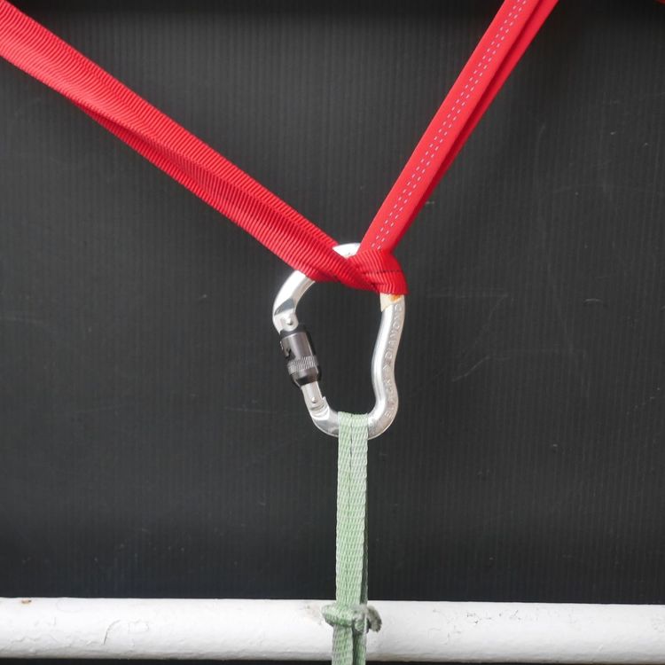 below (distant & close-up), 1/2"(?) dental floss vice the 1" 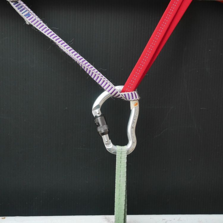 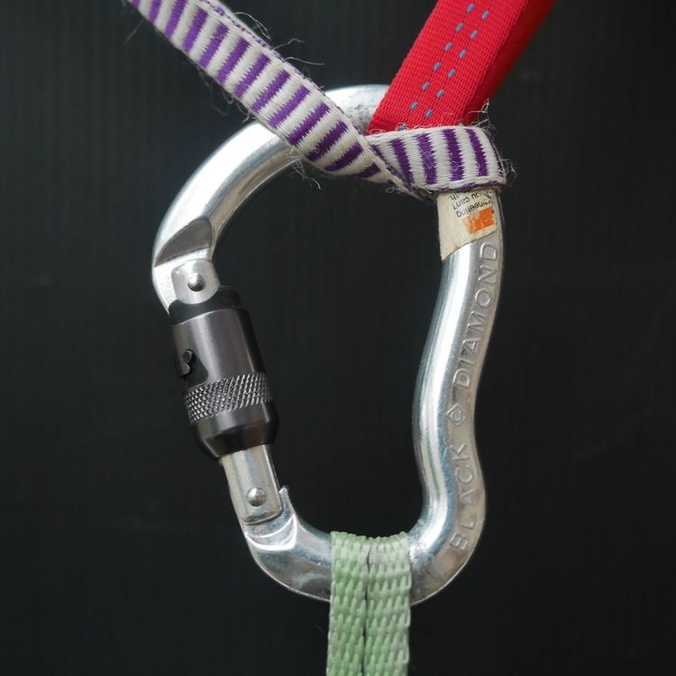 *kN* |
|
|
To determine were the loading is occuring you need to sum the loading vectors in the x and y directions (call y along the spine and x perpendicular). Next sum the moments about a point, say the center of the spine. Solving these sums should give you the load on the spine. This is a engineering mechanics problem. Generally easy to solve if all the lengths, locations, and angles are known but kind of tricky in the real world. |
|
|
Beyond 3-axis loading, it occurred to me that a similar "Spinal Tap" connection to an OVAL 'biner might considerably boost its strength for single-axis loading. And that I might try some quick'n'dirty testing of this thesis : so I used a (crummy) 5:1 pulley and stood in it with some shocking to boost force (maybe >700#?) and checked that (1) whereas normally oriented slings would lock the 'biner gate, it remained unlocked with the Spinal Tap connection; and I measured about a 1/4" (6mm) difference from where the away-from-spine edges of each tape fell. (Now, yes, getting say 30kN from a 'biner is hardly help if your attached slings break around 20kN, beyond needing such strengths anywhere near this neighborhood! touche' . So, I'm reaching for Brownie points for the Gee Whiz factor. :o) *kN* |
|
|
knudeNoggin wrote: Interesting! Maybe those slackline guys would test it... |
|
|
knudeNoggin wrote: Here are some images of this single-axis use of Spinal Tap. I've tried three cases : slings independent (not touching) --which I figure has vulnerability to sliding out of orientation--; slings overlapped & abutting at their U-turns; and then with the U-turns coming more apart, so that they wrap each other's outgoing arms. To my eye, there is a gain in this last case of how much out of the center point of the 'biner contact of exiting arms makes --and consider that this even is a sort of *glancing* blow, not a full-on wrap/grab of the 'biner arm! (And I include some example(s) of another tri-loading arrangement, which at least shows what bedevils an idle mind. ) Yes, the slackliners might see value in this. *kN* In the top image, I've marked (RED) where the edge of a normally attached sling edge would reach --centered at 'biner's arcing ends I marked in black where these Spinal Tap'd sling edges reached, showing their gain of moving spine-wards. (1/2" HMPE, 11/16" nylon (black, blue, or red)) 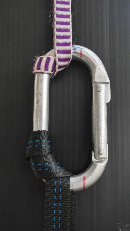 Okay, markings not conspicuous below. 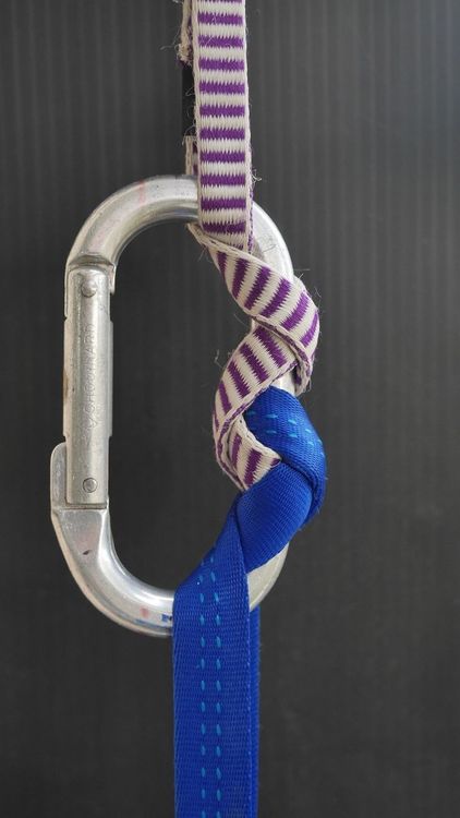 And below is the above, tilted a bit. 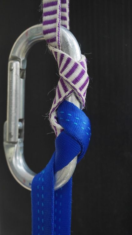 Finally, the *improved* interlocking of slings, which more elongates their wrapping, and seems to pull material more closely along spine. (I re-drew the tape-edge lines on the 'biner.) (In tying this, I put the HMPE (striped) sling on 2nd, pulling it through the red's U-turn wrap, with appropriate crossing.) 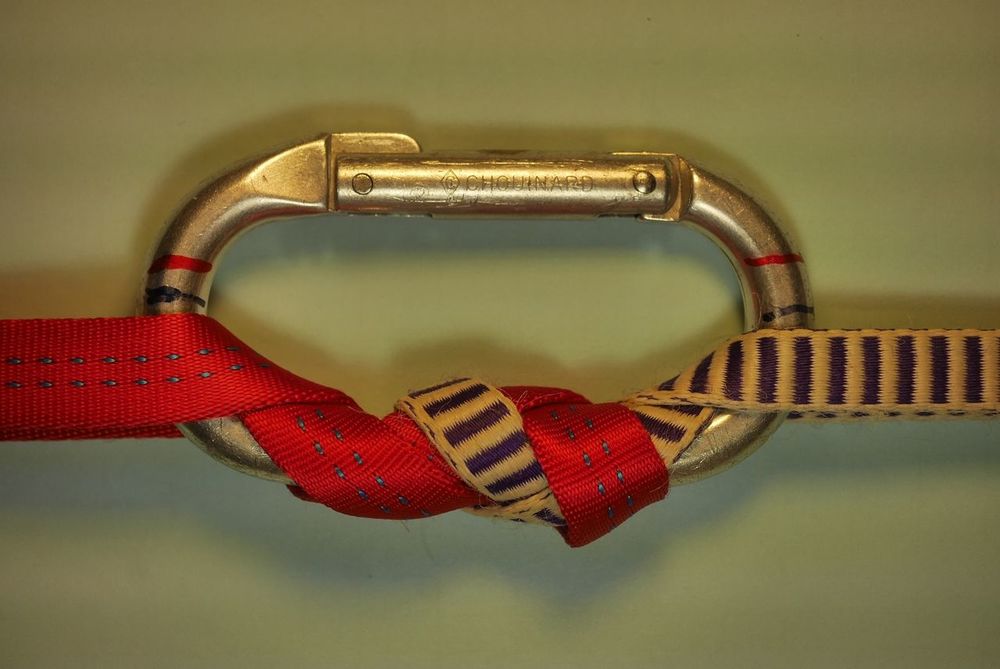 And that tri-loaded bedevilment : the striped sling clips into 'biner after the black, is brought over the black, then taps the spine. (There is but single strand around the spine,) 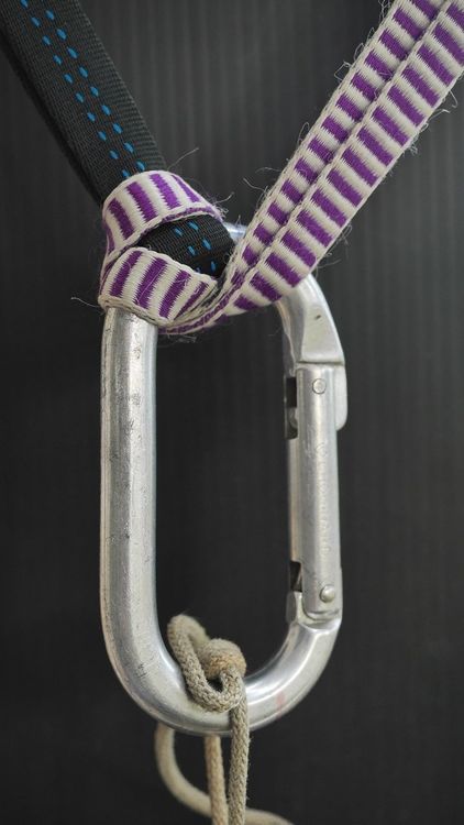 |
|
|
knudeNoggin wrote: Where the hell did you get a Chouinard carabiner??? |
|
|
knudeNoggin wrote: I'm suprised at you using "tri-axial" when it's clearly bi-axial! Just because climbers use the wrong terminology there's no reason for us to do so Doubling the tape over itself weakens it massively, the pressure from the outer layer cuts the inner one. About half the original strength is a rough guide, slackliners have this problem with small-diameter line lockers and I discoved the effect testing ground anchors one day when I casually shortened a sling. Neat idea though! |
|
|
Buck Rio wrote: In the golden old days. Older & golder, one could get Goldline! (-; 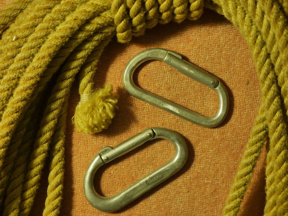 |
|
|
Jim Titt wrote: Well, I'm pretty simple, and see 3 unaligned directions; and to say "axis of tension" leaves me wondering how to figure just two!? The note about tape-upon-tape structures awakens a question I'd had. Hmmm. Bit of search for Wrap-3-Pull-2 and I find that "SAR3" has tested both this anchor structure and basket hitching (in common they present 4 strands (2 x 2 legs of bights) in load support, with one bight usually atop the other at the clip-in end. And these figures match your note, 7-11k. Here's the URL >>> https://app.box.com/s/n0tebq7vxq3mcu1wgxf21ayr5oysal7m The report cites TWO breakpoints in many basket hitches and in some few W3P2 ones; and it claims "In all trials the anchors broke at the screw link and not at the knot," but their on-line video of (only W3P2) breaks shows something IMO clearly NOT at the screw link (as tape for the 2nd --by a minute!-- break remains hanging through the link! !? <huh?> --my first glance at this. (@01:32..02:42) video here At 0:49 (YMMV) one can see distinctly TWO broken pieces, from W3P2. .:. Most interesting. (Would that they'd thought to mark the tape and noted under/over segments.) They assert statistically significant difference of greater strength (though slight) for the basket hitch over W3P2; they muse about readier force adjustment of strands, which seems dubious (though the joining knot will see greater load, have more compression, and only 90+deg. of surface contact for friction, vs. 270+ for W3P2). There is a difference in how the material arrives through the screwlink :: for BH, the two bights are at the angle of engagement; for W3P2, they are different only by the difference set at the anchor (one wrap above/below other, i.e.) --i.e., not much. In this threadspeak, there's more tri-bi-axialism in the basket (unless one works to have broadly spaced Wraps for W3P2!). !? --and these into a visibly curving-into-tape screwlink (not some broader 'biner curve or a straight machine pin). But as for this pressure-cutting factor, the orientations I've presented above don't put the *planes* of crossing contact-patches at right angles to the, um, axis(es) of tension. --a help?! *kN* |
|
|
Tl;dr- yes, nosehooking carabiners, even lockers, will produce the lowest breaking forces. |
|
|
Buck Rio wrote: You can get em for $20 off eBay, I've got a booty collection of em half a dozen deep |
|
|
We had a discussion on bi- or tri-axial In March 2018. As an engineer I think it's bi-axial and plenty others agreed and pointed out that if its tri-axial loading and one force (load) is removed then it must be called bi-axial loading. Remove the other load it's then single axis loading even though there is actually no load. I even found this cool bi-axial testing machine, that's what the manufacturers called it even though it's 16 load points on a ring. There are only forces applied in one plane with two axes. |
|
|
Jim Titt wrote: Does it help then to say that there are (are there?) three force vectors ?! (maybe each one with its own cordage & color!) *kN* |


