
 Continue with onX Maps
 Continue with Facebook


Holding power - what does it mean and how does that differ from a fall rating?


|
|
J C wrote: Good post. The only caveat I would add here is that it's not a pure sliding friction situation, so there are some design features which can potentially impact "holding force" by increasing "friction" or some aspect related to preventing the cam from sliding on the rock:
|
|
|
wivanoff wrote: Well, yes and no. That is a simplified model of friction, and it's reasonably accurate as an approximation in many cases. But, it is simplified. Nonetheless, the "more surface area" proponents have not really given any supporting data for why more surface area would be beneficial, nor proof that surface area is the strength limiting factor in typical placements. There are lots of reasons that a cam placement can fail. Sliding out due to insufficient frictional force is one of them, but not the only one. It can also have plenty of friction, for example, but the contact area of the lobes could simply tear off (shear stress failure) and result in the cam coming out.
Everything deforms under load (literally everything, and under any load) so it's not inherently catastrophic. The question is more rooted in the nuances of how much deformation occurs, and whether that deformation is fundamentally important to exactly how much load that the cam can withstand. |
|
|
Boy this thread went in deep. I agree with Kyle and Jonathan. The term "holding power" actually makes me cringe a bit because power is derived from energy transfer over time but holding "power" is always used in reference to some force. Maybe "holding force" would be better?? |


|
Yoda Jedi Knight wrote: Yep. "Power" in this case is more of a colloquial term, not a scientific one. |
|
|
wivanoff wrote: Sorry if I was unclear - I was only addressing the “line contact” comment, and did not mean to suggest that the increased surface area would result in increased friction. DMM seems to think that more area is good, see the widened lobes on Dragon 2 cams, but I have no information on why they made that choice. I agree that lobes deforming sounds like the beginning of a failure mode. I’m venturing into conjecture here, but I wonder if lobe deformation provides some boost in the strength of the placement as it approaches failure? |
|
|
wivanoff wrote: In a loaded cam the forces are such that the simple laws of friction are worthless, once the asperities start to deform then it's a whole new ballgame. |
|
|
Kyle Tarry wrote: You seem to be hyper focusing on lab placements that don't involve imperfect rock, and also making incorrect claims. More surface area potential of a cam definitely adds to the holding power safety of a cam in weaker rock. Metolius fat cams wouldn't exist otherwise, and the owner explains in a video about them that it's quite hard to lab test that type of stuff. Increased surface area potential adds to the room for error if the cam happens to be resting on something that might fail when it gets loaded if too much pressure is on it. It spreads the load out on the rock to make the cam less likely to break weak rock, or possibly catch elsewhere if a rock crystal it's resting on happens to break. You're right that it doesn't do much for something like bomber granite. I also openly said that I know there's more factors on what causes can angle differences to change besides more surface area. Can you explain why lower angles give more power? Its something I've been meaning to look into bit never have, yet. The deforming of cams that have softer metal (aliens) is sacrificing durability in exchange for a better bite on the rock. Lots of people buy them specifically because of that |
|
|
Wider lobes (more surface area) can help prevent a cam from pulling out in a couple ways. It reduces shear stress on the lobes. Shear stress can be simplified as F/A. In this case the force is the axial load on the stem, and the area is the cross-sectional area of the lobe under shear. The force will remain the same, but the area increases with the width of the lobe, reducing the shear stress on the lobe. Having wider lobes also reduces the compression on the rock. The pressure on the rock exerted by the outward force of the lobes can crush the rock supporting the cam. This pressure is again a function of F/A. This time the force is the outward force of the lobes and the area is the area of the lobe in contact with the rock. Wider lobes reduce the pressure on the rock reducing the probability the rock will crush. A smaller cam angle increases the outward force applied to the rock. Think of it as a lever. Moving the fulcrum toward the load being lifted exchanges displacement for increased force. i.e. a lever with a 10:1 ratio, if 10 N are applied over 1 m the lever will apply 100 N but only move the load 10 cm. Just like the lever, cam angle is a trade off between outward force applied by the cam and the cam's expansion range. Cams with lower cam angles produce more outward force but have smaller ranges. There are ways to increase expansion range without sacrificing expansion force like double axle cams and the totem design but even with those cams a change in cam angle will still have the same trade off. |
|
|
Have to say, the majority of you casual equipment engineers are a majority correct. Tough to accurately characterize a multi variable problem with all variables changing in time. Even harder when combined with loosey-goosey word definitions. Here’s my stab at answering the OP “Holding Power” = describes the cams ability to transfer energy to stay in place where you put it after a fall. Caveats- in short, its “Stayinplaceability” it’s not universal and different cam designs may be better for different rock types and types of placements. Probably Meaningless really, outside of a specified lab test or condition “Fall Rating” - the max force the cam can hold before mechanical/material failure, assuming the cam Stayed place. Basically breaking strength Fall rating is always > Holding power |
|
|
Kyle Tarry wrote: Yes, I agree, the material(s) affect the friction against rock, and the lobes may be structured for mechanical keying of the lobes in the rock. I'm skeptical as to whether there are many gains to be made here. And either way, I want to use my cams well past the surface pattern wearing away. As for the Metolius Fat Cams- I haven't watched the video, but just because the owner said something doesn't mean he knows any more physics than the people on this thread. I don't have a particularly advanced knowledge of tribology, but it's my understanding that for human-scale objects, moving not too fast, that surface area has no effect on the force of friction. Wider lobes lead to lower pressure on the rock. This could be advantageous, because pressure is the key factor in rock failing in compression. Ever bought concrete? It's rated in PSI (if you're in America). That is pressure. |
|
|
Any kind of discussion of cam holding power seems to require a lot of arm waving and opinioneering. I've never seen a standardized test for this, have any of yall? For you engineer types: Given some of the variables (cam width and material, type of rock, type of constriction or flair, etc.) how could a standardized test be applied across cam size ranges, makes and models? I imagined a test device consisting of a flared, outwardly curved crack surface. I imagined a standard one made of specific concrete mix, and conceivably ones could also be made from various types of stone. I am thinking the key is the outwardly curving flair. Tough to find examples of this on an image search, but when looking at logarithmic spirals I came across this: 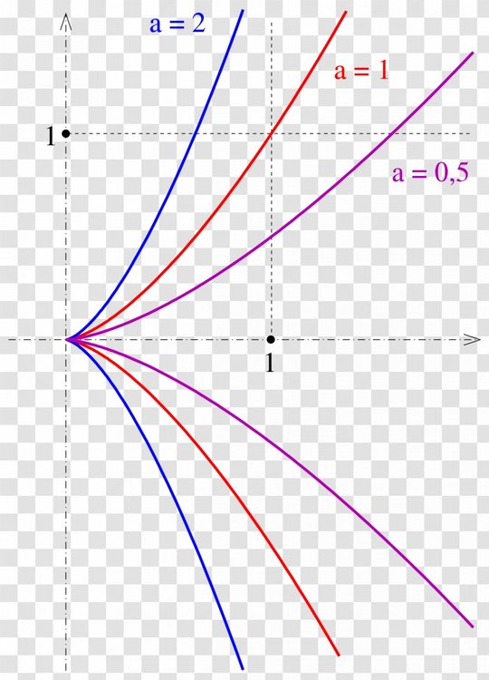 imagine that is the cross section of our outwardly curved flaring crack, looking down from the top. Cam is inserted and then pull tested in 3 places, nearly fully retracted, exactly half-way and then almost fully opened. Increase pull force (on the x axis, pulling in the direction of the arrow) until the unit comes out. Record. Wash rinse and repeat for every size cam in the cam collection. Record and average across all the cam sizes for a particular model. Then do the competitor's cams, same test, record the results and average. The coefficient might be something more like a=.25 or whatever. This give our constant angle cam a constantly curved surface upon which to hold and would provide a level playing field for various cam designs, minimizing or eliminating rock substrate variables along the way. And if you fashioned a test crack out of a few different stone types, then perhaps even the rock type holding power could be quantified as well? I suspect such a test could be designed to favor one cam design over another? |
|
|
Erik Strand wrote: i don't really see anything incorrect in what he is posting. he is talking about "typical" placements, probably in an effort to keep things simple and not get too far into the weeds. sure, there are all sorts of potential scenarios where any and all of these variables and their effect on the outcomes can be contradictory. for example, the metolius fat cams. theoretically they spread the force over a larger area and reduce the stress, which can be theoretically beneficial if you have rock with low compressive and/or shear strength. On the other hand, a hard material with a wide surface might not take the best advantage of the tribology of a rock surface when you want the material to deform to the surface irregularities. there really isn't a right answer. fat cams have never really caught on that big though, probably because you see people falling on desert sandstone fairly routinely with all sorts of different cams. and fat cams are heavy. one thing that is kind of funny with the fat cams - metolius advertises their camming angle as producing a larger normal force saying it has better holding power, then comes up with fat cams to reduce the stress from the increased normal force. luckily the cam range is reduced in the process... :( but getting back to the original question, like others have said these are so different it is like comparing apples and lawn furniture. |
|
|
and to think...if you just placed a hex to begin with, you wouldn't have to worry about all this nonsense... |
|
|
J C wrote: There is a difference between the theoretical model of cam use and a practical analysis of the mechanism of cam failure. If I'm not doing justice to Custer's analysis, I'm sure he'll correct me. Theoretically, you have contact just along a transverse line on the cam lobe surface, and the design of cam lobes and in particular the logarithmic spiral cam shape is based on this ideal view. In reality, assuming there isn't a mechanical failure of some part of the cam structure, what happens as the outward force increases is that there is a flattening of cam lobe in a small region around the line of contact, so that you have a small rectangular patch of the deformed cam lobe surface in contact with the crack wall. In terms of this patch, cam failure is described in terms of shear forces on the rectangular patch. What happens is not a failure of friction, which in theory cannot happen, because resistance due to friction is proportional to the normal force and so would never yield to an increase in normal force, but rather a shearing flow of cam material that causes the cam to slide out. The size of the rectangular contact patch on the cam load is affected by the magnitude of the outward force. Assuming the same load to the piece, a lower camming angle produces higher outward lobe forces and these in turn create somewhat bigger deformed contact areas. On thing affecting the deformation of the cam under load is the hardness of the cam material. Softer materials seem to "bite" better at low loads but will fail sooner at high loads. I think this was a feature of Aliens, for example. |
|
|
Kyle Tarry wrote: Yup. One of the unresolved inconsistencies of cam "science" is that their design comes from the classical friction description in which surface area plays no part, but there is a vague or maybe not so vague sense that other factors that aren't present in the classical model can have some effect. Anodizing seems to reduce the classical coefficient of friction associated with the cam lobe material. Physical surface treatments grooves, cross-hatching, etc., to the extent that they do something, they negate the classical friction assumptions, because those treatments don't simply increase the coefficient of friction, they change the way friction operates. This is why the coefficient of friction analysis has little to tell us about the friction of climbing shoe rubber against rock. Increasing surface area reduces pressure, which isn't part of the coefficient of friction concept. But pressure does have something to do with what the cam is doing to the crack surface, and increasing cam area reduces pressure and so perhaps keeps the cam from "channeling" a soft surface and so failing in that way. This last example illustrates how the concept of "holding power" is complex and possibly not even a feature of the cam in isolation from its placement. |
|
|
Erik Strand wrote: Hold on a second though; we weren't talking about cam lobe width or fatcams or any of that. We were talking about camming angles, and you made two very specific claims that I am asking you to explain: 1. Lower camming angles mean larger contact area 2. That increase in contact area is the primary mechanism for increased "holding power" of a lower camming angle. Let's get those two things sorted out, before we go off on a tangent about fatcams, rock destruction, or lab placements.
As I mentioned upthread, lower camming angles increase the outward force that a cam applies onto the crack, which can (in some situations) feasibly increase its resistance to sliding out due to insufficient friction (regardless of which friction model you're choosing to believe). It's possible that this could increase holding power in SOME placements, where the friction is the limiting factor, the rock and cam can withstand the additional force, and the additional force does actually increase friction. Reduced cam angle also does other things, and they aren't all good. Perhaps the higher normal force just breaks the rock. Perhaps the reduced range of a lower cam angle means the placement fails after the rock and/or cam deforms under load. In the end, making a blanket statement that lower camming angles "hold better" is really questionable, because the situation is complicated. |
|
|
rgold wrote: While it's not my intent to pick on Dave, I doubt both the validity and the usefulness of the model and conclusions presented on his page. Bear with me and I will try to explain why: Validity: The page's conclusion is that cams will fail due to shear failure of the lobe at the lobe-rock interface, and that this failure will happen in the range of 3kN-8kN in a significant number of scenarios. Yet, in the idealized lab scenario (the closest thing we have to the model assumptions), this does not appear to be the case. Watch all the BD test videos, the cams rarely (never?) fail due to shear failure of a small area of the cam lobe, and the cams eventual failure happens at higher values than what this model predicts. If your model fails to predict your experiments, it ought to bring the model into question. Usefulness: In the real world, when cams fail (and people get hurt, which is fundamentally what we care about), it's rarely due to shear failure of the tiny Hertzian contact area. Cams come out under climbing loads due a a variety of other factors, such as insufficient range, expanding flakes, slippery rock, cam head deformation, walking into a poor placement, umbrella-ing, rock failure, etc. Given this, what's the utility of a long analysis predicting that cams will fail in shear in the idealized elastically-deformed contact area? I'd argue that there isn't much utility at all.
Perhaps true. Note that there are different material properties involving "hardness" and "deformation" in their colloquial usage; there's the bulk flexibility of the material, which is described by the modulus of elasticity and poisson's ratio (the properties used in the Custer analysis) and there is the resistance to surface deformation/indentation of a small object as per the Rockwell/Vickers/Brinell/etc. hardness test, which I believe is what you are talking about here. We must be careful not to mix and match these terms and mechanisms. |
|
|
Kyle Tarry wrote: All I was trying to do was to explain Dave's claim that smaller camming angles result in higher surface area contact because of lobe deformation. I've actually watched Aliens tested in a jig and I'd say there is absolutely no question that shear yield failure is what happens in that case; they actually left an aluminum slick on the jig surfaces. In the BD tests the "crack walls" move; who knows what that does to the shear yield results, but it is conceivable that they delay it as the force builds. And of course general validity and relevance are, as with any model, complex. Is the model all wrong do the parameters need adjusting, or some combination of both? |
|
|
Keep it simple. Aside from non-camming failures (bad placement, total mechanical failure of cam), all cam failures from pulling are a result of the climber’s fall force (shear forces) exceeding the retarding friction force. The friction force becomes exceeded when the normal forces exceed the mating materials’ (rock and cam lobe material) asperities compressive and shear strengths and turn into little ball bearings and starts a chain-reaction As the cam begins to move. The resulting kinetic friction is still scrubbing energy from the fall for a few micro seconds but the die is cast, the cam has “blown” and is on its way out of the crack. Not sure how any of this helps us at all. End result is same. Place cam, clip, hope for the best. |
|
|
rgold wrote: There's no doubt that more force means more deformation; that's materials 101. But the claim is that this (tiny) increase in the hertzian contact area is the primary mechanism for increasing holding capability (with a smaller cam angle). I am questioning that.
I believe this. However, that's not necessarily the same as Dave's calculated shear failure forces using the Hertzian contact area as the loaded zone. If you scrape a large volume of material off the lobe surface, you're actually proving this wrong, since the calculated Hertzian area is so tiny, if you scrape a bunch of material off the failure mode must be something different. Here's a video of a pull test of Totem Basic cams (Alien clones), which do not fail in this manner, but instead fail due to stem failure (at higher loads than the predicted shear failure) or umbrella-ing (a different failure mode entirely): https://youtu.be/qIAZ4DFyUNQ?t=75
If you're putting a given force on the cam, it's putting a certain force on the crack walls that is a function of the cam angle (and some other factors like friction in the head, etc.). It doesn't matter if the crack is deflecting or not, load on the lobes is the same for a given pull force. However, there are possibly things going on which are in direct conflict with the assumptions of Dave's model. For example, if the crack wall (real or test rig) deflects/deforms such that it takes on a curvature and significantly increases contact with the lobe, the assumption of Hertzian contact area is completed nullified and the attached assumptions about shear failure become void. The cam could still fail due to material shear failure, but in a mechanism completely unrelated to Hertzian stress and completely outside the bounds of that proposed model.
The model asserts that shear failure of the cam lobe in the Hertzian contact area is the primary mechanism for placement failure. I believe this bounding assumption to be incorrect, and I believe that there is ample test data to support this, primarily the fact that the vast majority of cam tests show other failure modes, and the fact that cams fail at higher loads than predicted by this model. I also believe that this (Hertzian contact area) is pretty much the last thing climbers should be worried about when placing cams. |


